- EQUIPMENT
-
special cranes
-

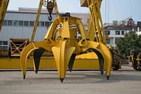
Garbage Grab Crane
-

Foundry Overhead Crane
-

Explosion-proof Overhead Crane
-

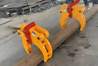
Tongs Overhead Crane
-

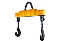
Overhead Crane with Carrier-beam
-
Electromagnetic Overhead Cranes
-

Diesel Hydraulic Straddle Carrier: Flexible Operation and Affordable Solution for Container Handling
-

Upper Spillway Gate Gantry Crane: Reliable Solution for Dam Gate Hoisting and Hydropower Station Operations
-

Harbour Portal Crane: Powerful and Intelligent Solutions for Efficient Port Handling
-

Coke Pot Crane for CDQ: Exceptional Heavy-Duty Red-Hot Coke Handling
-

Emergency Rescue Specialized Crane for Water-Rescue Simulation: Engineered for Lifesaving Training
-

Intelligent Grab Bucket Overhead Crane: Powerful, Precise and Unmanned Bulk Material Handling Solution
-

Custom Multi-Point Suspension Overhead Crane for Large-Span and Load-Sensitive Industrial Buildings
-

Electrolytic Copper Cranes: Specialized in Efficient Cathode Plate Tank Loading and Transfer
-

Nuclear Polar Cranes: Multi-Function Lifting Machinery For Nuclear Power Plants
-
-
Industry Crane
-

Industry Crane
-

Tundish Cranes
-
Slab Cranes
-

Scrap Cranes
-

Billet Cranes
-

Coil,Bar and Plate Handling Cranes
-

Cement And Precast Crane
-

Power Station Crane
-

Ladle Cranes
-

Paper Industry Cranes
-
Waste to Energy Cranes and Biomass Cranes
-
Tailored Overhead Cranes for Aerospace: High Precision, Efficience, Safety and Reliability
-

Anode Baking Multifunctional Cranes: Versatile, High-Temp Resistant & Smart-Controlled Must-Have for Electrolytic Aluminum Industry
-

Multifunctional Crane For Electrolytic Aluminum: Fulfills All Aluminum Electrolysis Processes, Boosts Plant Efficiency
-

Warehouse Stacker Crane for AS/RS: High-Efficiency, Reliable, Fully Automated Storage
-

Slab Handling Overhead Crane: Metallurgical-Grade Crane for Continuous Casting and Slab Yards
-

Anode Carbon Block Stacking Cranes: 6-Layer Stacking, A Lifting Solution for Carbon Plants’ Efficient Transfer
-

Quenching Crane for Heat Treatment: Process-Oriented Overhead Crane Solution
-

Safe & Stable Scrap Charging Overhead Crane for Metallurgical Feeding Operations
-

Forging Overhead Crane: Reliable Lifting Equipment for Heavy-Duty Forging Workshops
-

Mold Handling Crane for AAC Production Line: Reliable Engineered Fixed-Position Lifting Solution
-

Pickling Overhead Cranes: For Acid Mist Environments in Non-ferrous Metal Smelting
-
-
Hoist & Winch Trolley
-
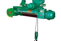
Casting Electric Wire Rope Hoist
-

European Model Electric Hoist
-

Explosion-proof Electric Hoist
-

Low-headroom Electric Hoist
-

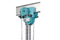
Electric Chain Hoist
-

2 Types Explosion-Proof Electric Chain Hoists for Hazardous Zones: Gas & Dust Protection
-
2 Types Explosion-Proof Electric Wire Rope Hoists for Industrial Safety: Reliable Gas & Dust-Proof Solutions
-
Manual Hoists for Precision Lifting: Explore 3 Proven Types for Power-Free Operation
-

Air Pneumatic Hoists: 4 Specialized Designs for Precision, Safety, and Harsh Environments
-

HC Type Electric Hoist: Heavy-duty Wire Rope Hoist for Factory Heavy Lifting
-
-
CRANE Spreader
-
Crane Electromagnetic Lifting Magnets
-

Lifting Electromagnet for Turning and Side Hung
-

Lifting Electromagnet for Thick Plate
-

Specialized Electromagnet for Lifting Steel Plates
-

Lifting Electromagnets for Lifting Steel Plates
-

Lifting Electromagnet for Heavy Rail and Profiled Steel
-

Lifting Electromagnet for High Speed Wier(Coiled Bar)
-

Lifting Electromagnet for Rebar and Steel Pipe
-

Lifting Electromagnet for Bundled Rebar and Profiled Steel
-

Lifting Electromagnet for Billet, Girder Billet and Slab
-

Lifting Electromagnet for Steel Scraps
-
- Crane Spreader
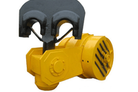
- Crane Hook
- Crane Lifting Tongs and Clamps
-
Crane Electromagnetic Lifting Magnets
- CRANE PARTS
- Transfer Cart


.png?w=200&h=134)


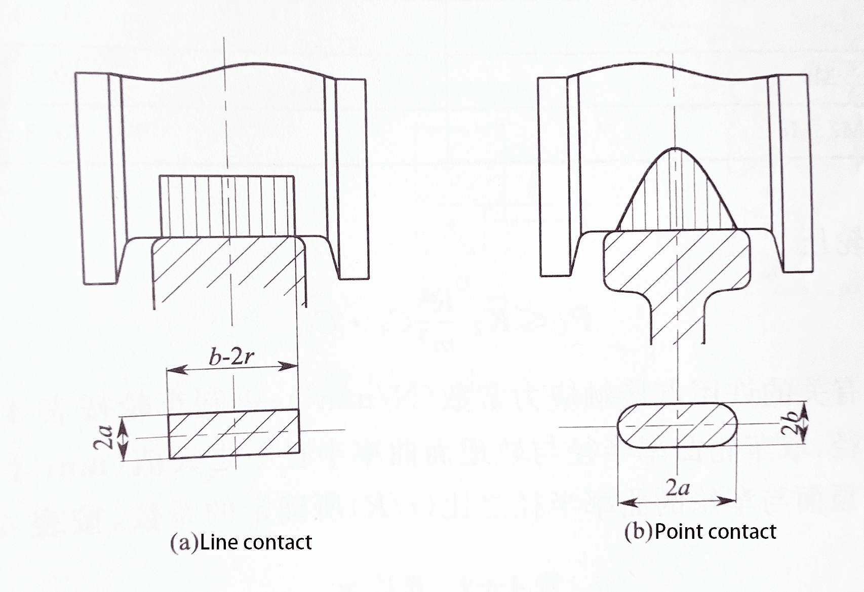 1. Allowable wheel pressure for line contact:
Pc≤K1×D×L×C1×C2
Where
PC —- wheel fatigue calculation load (N);
K1 —– material-related permissible line contact stress constant (N/mm2), selected according to Table 1;
D —– wheel diameter (mm);
L—— effective contact length between wheel and rail;
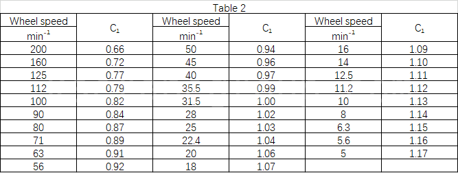
C1—– speed coefficient, selected according to Table 2;
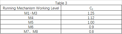
C2—– working level coefficient, selected according to Table 3;
2. Allowable wheel pressure for point contact:
1. Allowable wheel pressure for line contact:
Pc≤K1×D×L×C1×C2
Where
PC —- wheel fatigue calculation load (N);
K1 —– material-related permissible line contact stress constant (N/mm2), selected according to Table 1;
D —– wheel diameter (mm);
L—— effective contact length between wheel and rail;
C1—– speed coefficient, selected according to Table 2;
C2—– working level coefficient, selected according to Table 3;
2. Allowable wheel pressure for point contact:
 Where
PC—- wheel fatigue calculation load (N);
K2 —– material-related permissible point contact stress constant (N/mm2), selected according to Table 1;
R —– curvature radius, take the wheel radius of curvature and track radius of curvature in the larger value (mm);
M—— ratio of the top surface of the track to the radius of curvature of the wheel (r/R), selected according to Table 4;
C1—– speed coefficient, selected according to Table 2;
C2—– working level coefficient, selected according to Table 3;
Schedule of calculated coefficients:
Where
PC—- wheel fatigue calculation load (N);
K2 —– material-related permissible point contact stress constant (N/mm2), selected according to Table 1;
R —– curvature radius, take the wheel radius of curvature and track radius of curvature in the larger value (mm);
M—— ratio of the top surface of the track to the radius of curvature of the wheel (r/R), selected according to Table 4;
C1—– speed coefficient, selected according to Table 2;
C2—– working level coefficient, selected according to Table 3;
Schedule of calculated coefficients:
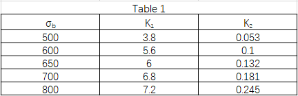 Note:
1. σb is the tensile strength of the material (N/mm2);
2. Steel wheels should generally be heat-treated, tread hardness recommended for HB = 300 ~ 380, quenching layer depth of 15mm ~ 20mm, in determining the permissible value, take the σb when the material is not heat-treated;
3. When the wheel material adopts ductile iron; σb.≥500N/mm2 material, K1, K2 value is selected according to σb.=500N/mm2.
Note:
1. σb is the tensile strength of the material (N/mm2);
2. Steel wheels should generally be heat-treated, tread hardness recommended for HB = 300 ~ 380, quenching layer depth of 15mm ~ 20mm, in determining the permissible value, take the σb when the material is not heat-treated;
3. When the wheel material adopts ductile iron; σb.≥500N/mm2 material, K1, K2 value is selected according to σb.=500N/mm2.
 Note:
1. When r/R is any other value, the m-value is calculated by interpolation;
2. r is the small value of the radius of curvature of the contact surface
The above calculations can be used to verify the verification of the wheels of the set diameter, in order to determine the effective maximum bearing capacity of the wheels and the reasonableness of the dimensions (diameter of the wheels, wheels and rail with the dimensions, etc.).
Note:
1. When r/R is any other value, the m-value is calculated by interpolation;
2. r is the small value of the radius of curvature of the contact surface
The above calculations can be used to verify the verification of the wheels of the set diameter, in order to determine the effective maximum bearing capacity of the wheels and the reasonableness of the dimensions (diameter of the wheels, wheels and rail with the dimensions, etc.).
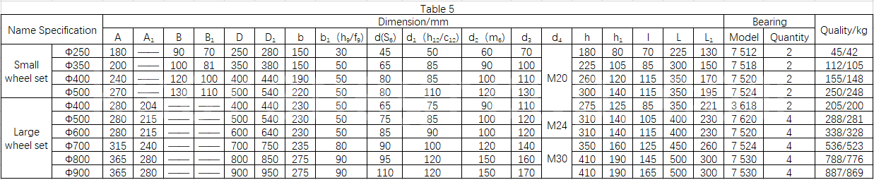
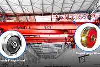
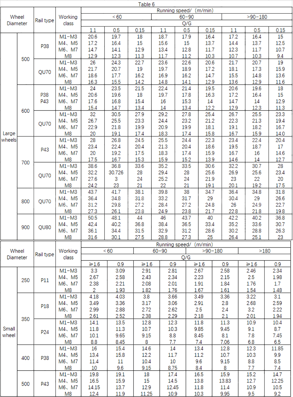 Crane wheel set series attached chart:


